Fault Tree Analysis (FTA) is a top-down, deductive analytical method used to understand how and why complex systems fail. Originally engineered within the aerospace sector, the practice of FTA is now a standard requirement across automotive, medical device, and industrial automation engineering, particularly where master standards like IEC 61508 and ISO 26262 make systematic risk management mandatory.
The primary utility of an FTA is to establish a clear, visual model using logical connections to map out complex failure pathways. By starting with a single, high-level undesired event and working backward to identify its underlying root causes, engineering teams can accurately evaluate risk profiles, identify architectural weak points, and optimize overall system reliability.
The Structural Architecture of a Fault Tree
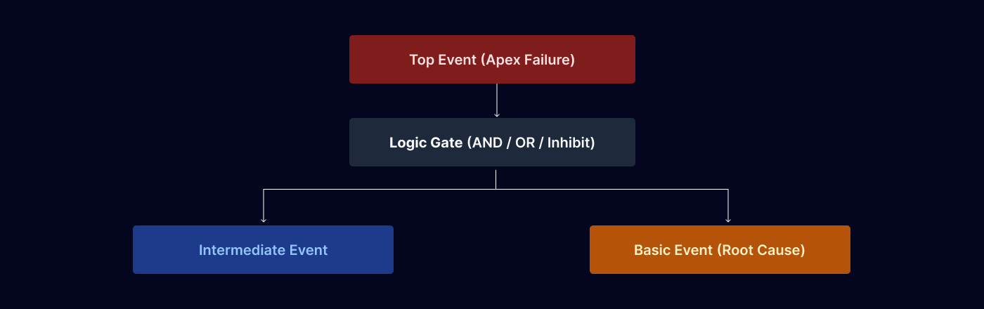
An FTA visually organizes systemic failure logic using standardized event definitions and logic gates to connect a primary system-level hazard to its low-level component triggers.
Step-by-Step FTA Execution Framework
Step 1: Establish the Analysis Objective
The initialization of an FTA requires defining a clear technical objective, which typically maps directly to a defined safety goal or a critical concern regarding system failure. Engineers must answer a single question: What specific hazardous condition am I trying to prevent?
Engineering Examples:
Preventing the unintended deployment of an automotive airbag subsystem, or preventing a commercial truck from driving off a drawbridge into a river. This core objective dictates the boundaries and depth of the entire deductive model.
Step 2: Formally Define the Top Event
The top event is the singular, definitive system-level failure under analysis, positioned at the absolute apex of the logic tree. Everything built beneath this event serves to explain the mechanisms of its occurrence.
Core Rules:
The top event must be highly specific and focus strictly on an actual operational failure mode. Architects must limit the tree to exactly one top event. If a system presents multiple separate safety concerns, engineers must construct completely independent fault trees for each unique condition.
Engineering Examples:
"Braking system fails to actuate on demand," "Loss of vehicle directional control," or "Hydraulic pump does not deliver fluid pressure".
Step 3: Establish Boundaries and Scope
Before executing the breakdown, teams must document explicit system boundaries to clarify what factors are included or excluded from the analysis. The scope definition must formalize:
The exact version, revision number, and schematic layout of the hardware system under review.
Whether the evaluation is restricted to hardware failure modes or incorporates software bugs and algorithmic execution logic.
The operational profiles being analyzed, defining whether the model evaluates normal runtime environments, specialized maintenance window configurations, or both.
Step 4: Calibrate the Resolution and Level of Detail
Engineers must determine the target depth of the tree before building out logic paths. An FTA can remain high-level, stopping at macro-level subsystems or functional block drops, or it can drill down into highly detailed component-level failure modes and individual part defects. The critical best practice is to maintain a completely consistent level of detail across all branches of the tree; if a specific path is analyzed down to component-level failure modes, all adjacent pathways must be driven to the same level of granularity.
Step 5: Enforce Labeling and Model Ground Rules
To maintain audit readiness and ensure seamless multi-team reviews, the engineering squad must establish strict ground rules regarding labeling and terminology before construction begins.
Deploy a simple, completely consistent alphanumeric naming convention for all logic gates and intermediate events.
Formalize standard modeling approaches for repeated events (fault paths that appear in multiple branches) or undeveloped events that do not require deeper analytical breakdown.
Enforce precise engineering terminology so all cross-functional stakeholders share an identical interpretation of the data.
Step 6: Construct the Fault Tree Model
Starting directly below the defined top event, engineers break the failure path down sequentially from top to bottom, linking causes via standardized logic gates. Each gate configuration must be completely resolved before moving deeper into the architectural layers.
Logic Gate Architectures:
* AND Gate: All inputs must occur simultaneously to trigger the output event.
* OR Gate: Any single input event is sufficient on its own to trigger the output.
* XOR (Exclusive OR) Gate: Exactly one input can occur, but never both simultaneously.
* Priority AND Gate: Inputs must occur in a highly specific sequential chronological order to trigger the output.
* Inhibit Gate: The output event occurs only if the input fault occurs while a separate conditioning factor is true.
Event Classification Typologies:
* Basic Event: A fundamental component failure or root cause that cannot be broken down further.
* External Event: A normal, expected environmental condition or operational state that is guaranteed to occur.
* Undeveloped Event: A complex failure mode that is recognized but not analyzed further due to scope limits.
* Conditioning Event: A specific operational limit or environmental factor that must be true for a gate to pass logic.
Construction Tip: Every event description inside the model must be written strictly as a definitive failure, never as a generic operational state. Complex interactions should be clarified using localized design notes embedded directly into the branch layouts.
Step 7: Execute Qualitative and Quantitative Evaluations
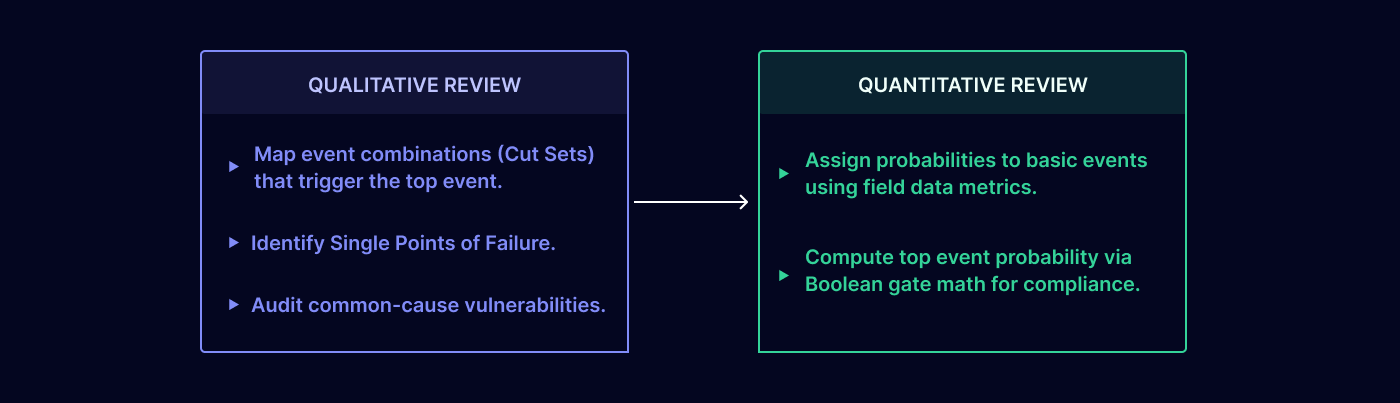
Once the structural model is verified, the fault tree undergoes a dual-layer evaluation process.
Qualitative Analysis:
This involves auditing the visual diagram to identify combinations of events that can produce the top event. Engineers search for minimal cut sets to expose single points of failure, structural design weak links, and critical common-cause failure vulnerabilities across redundant paths.
Quantitative Analysis:
Engineers assign empirical failure probabilities or historical failure rates to each underlying basic event. By applying Boolean algebraic logic laws through the connecting gates, software platforms calculate the exact probability of the top event occurring. This numerical output provides objective evidence to demonstrate system compliance with quantitative safety targets mandated by regulatory bodies.
Step 8: Document and Share Actionable Takeaways
The final phase of the FTA process involves transforming the mathematical and logical outputs into clear, actionable engineering takeaways for management and development teams. The final technical report must:
Highlight the most critical and high-probability failure pathways leading to the top event.
Propose targeted design mitigations, including adding physical component redundancy, implementing diverse voting logic, or introducing specialized diagnostic testing loops.
Demonstrate explicitly how the analytical findings either validate the assumptions of the existing system safety plan or challenge it, forcing architectural updates.
Core Engineering Rules for High-Integrity FTA
Enforce Logical Simplicity:
Avoid over-complicating the model. The vast majority of high-integrity systems can be modeled accurately using only standard AND and OR gate configurations.
Maintain Top-Down Discipline:
Never skip architectural layers or jump directly to components during construction. Build the tree methodically down from the top event, layer by layer.
Account for External Variables:
A comprehensive safety case cannot evaluate hardware in a vacuum. Engineers must actively integrate human operational errors, maintenance process slip-ups, and harsh external environmental conditions into the basic event tiers where relevant.