For designers of advanced robotic systems seeking IEC 61508 certification, executing a rigorous risk assessment according to ISO 12100 is a critical initial milestone. These two international safety standards do not operate in isolation; they are deeply complementary frameworks. ISO 12100 establishes the foundational, high-level methodology for establishing system boundaries, identifying physical hazards, and evaluating raw risks.
IEC 61508 builds directly upon this structural groundwork, specifying the explicit, high-integrity requirements for the electrical, electronic, and programmable electronic (E/E/PE) safety-related subsystems tasked with managing those risks.
Step 1: Defining Machinery and Operational Limits
The risk assessment lifecycle initiates with a comprehensive evaluation of the robotic system's absolute operating limits across all phases of its deployment lifecycle. This boundary documentation must be locked in before conducting hazard analyses and incorporates three primary vectors:
Physical Limits:
Documenting the robot's physical reach, total range of motion, mechanical velocity profiles, and kinetic force capabilities.
Time Limits:
Defining the expected operational lifetime of the system, component wear-and-tear thresholds, and mandatory preventive maintenance intervals.
Use Limits:
Outlining all intended operational modes (such as automatic operation, high-speed sorting, or manual bypass), foreseeable misuse conditions, and predictable human-machine interactions.
Application Focus (Collaborative Articulated Arm): For a collaborative robot arm deployed in an industrial manufacturing work cell, the engineering file must document specific boundary metrics. The physical parameters establish a 1.4-meter reach, a 15-kilogram payload threshold, and a 1.5 m/s maximum operating speed. The time boundaries outline a 10-year expected design lifecycle backed by mandatory quarterly maintenance intervals. Use parameters restrict operations to pick-and-place trajectories alongside direct human interaction during manual teaching phases.
Step 2: Systematic Hazard Identification
Engineers must systematically identify all potential hazards, hazardous situations, and hazardous events native to the robotic cell. This analysis must categorize risks into distinct engineering domains, evaluating mechanical hazards (crushing, shearing, or high-velocity impact), electrical hazards, thermal hazards, and control system failures.
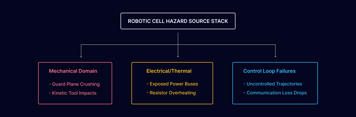
For a standard collaborative assembly robot, this identification layer exposes critical risk events:
Crushing hazards emerging between the moving robot arm structure and adjacent fixed mechanical infrastructure or work cell walls.
High-velocity impact hazards resulting from unexpected or unprogrammed movements during trajectory errors.
Electrical shock hazards stemming from exposed power terminals or internal bus connections during active maintenance routines.
Control system faults causing a total loss of path control, resulting in erratic, high-speed uncontrolled motion profiles.
Step 3 & 4: Risk Estimation and Evaluation Parameters
For every identified hazard, engineers execute a risk estimation loop to derive a qualitative or quantitative risk index. Under the ISO 12100 framework, risk is evaluated as a combined function of the severity of potential harm and the total probability of its occurrence. This probability metric is mathematically weighted by examining exposure frequency/duration, the probability of the hazardous event manifesting, and the realistic possibility of human avoidance or limitation.
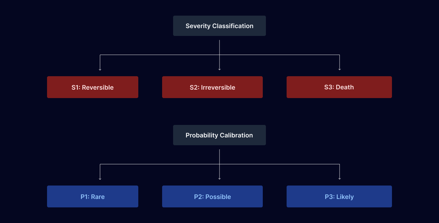
Severity Levels:
Indexed from S1 for minor, completely reversible injuries; S2 for serious, irreversible permanent injuries; up to S3 for fatal outcomes.
Probability Levels:
Calibrated from P1 for rare occurrences; P2 for possible events during standard operation; up to P3 for highly likely failure profiles.
During the risk evaluation stage, this combined index dictates whether active risk reduction measures are mandatory to satisfy safety targets. For example, a crushing hazard located between a robot arm and a rigid workpiece is rated at a serious severity level of S2 and an operational probability level of P2 (possible during normal manual manipulation), yielding a definitive result: risk reduction required.
The 3-Step Risk Reduction Hierarchy
When a robotic hazard requires active mitigation, engineers must apply the non-negotiable three-step hierarchy of controls dictated by ISO 12100.
1. Inherently Safe Design Measures
This priority phase requires engineering the hazard completely out of the system at the source by modifying the robot's physical architecture. Techniques include modifying mechanism geometry to eliminate pinch points, structurally limiting maximum force and speed capabilities, integrating mechanical hard stops, and utilizing fail-safe engineering principles. In collaborative robotics, this translates to designing rounded external edges, smooth geometric surfaces, restricting joint torques directly through mechanical design limits, and implementing back drivable joints.
2. Safeguarding and Complementary Protective Measures
Hazards that cannot be completely eliminated without destroying the machine's utility must be managed via electronic and electromechanical safeguarding systems. This layer incorporates physical perimeter guards, safety interlocks, emergency stop networks, safety-rated monitored stop functions, and active speed and separation monitoring loops.
Practical implementations include deploying industrial safety laser scanners for perimeter presence detection, integrating pressure-sensitive mats within the active tool center point (TCP) operating zone, and configuring hardware-isolated two-hand control devices for hazardous maintenance configurations.
3. Information for Use
The final defensive layer manages the remaining residual risk through administrative controls and clear communication. This layer must never substitute for proper safeguarding or inherently safe design engineering. It requires permanently mounting warning signs and acoustic/visual signals, establishing strict operating procedures, mandating technician safety training, and compiling comprehensive maintenance instructions.
Transitioning to IEC 61508: SIL Assignment Mechanics
The safeguarding measures established in Step 2 of the hierarchy often rely on complex E/E/PE control loops. To certify these safety-related systems under IEC 61508, the foundational ISO 12100 risk parameters must map directly into a quantitative Safety Integrity Level (SIL) assignment matrix. This derivation requires a structured four-stage evaluation:
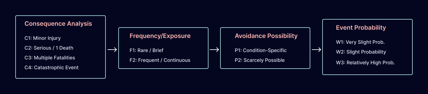
Step 1: Consequence Analysis ($C$):
Evaluated from C1 (minor injury), C2 (serious permanent injury to one or more persons, or death to a single operator), C3 (multiple fatalities), up to C4 (widespread multi-fatality catastrophic events).
Step 2: Frequency and Exposure Time ($F$):
Calibrated from F1 (rare to brief exposure profiles) to F2 (frequent to continuous exposure inside the danger zone).
Step 3: Possibility of Avoiding Hazard ($P$):
Rated at P1 (possible under specific, deterministic operational conditions) or P2 (scarcely possible due to rapid event development).
Step 4: Probability of Unwanted Occurrence ($W$):
Quantified from W1 (very slight probability), W2 (slight probability), up to W3 (relatively high probability of failure manifestation).
SIL Assignment Calibration Example: For a robotic cell's primary emergency stop function, the consequence analysis registers a potential single-operator fatality scenario, classifying it as C2. The exposure profile is frequent, returning an F2 index. Due to the automation speed, the possibility of physical avoidance is scarcely possible, yielding a P2 rating. Assuming a standard system configuration, the probability of an unwanted occurrence is determined to be slight, indexing at W2. Plotting these four verified parameters into the IEC 61508 safety allocation framework yields a mandatory SIL 2 requirement for the control system architecture.
Risk Reduction Verification and Validation Lifecycle
For every implemented electronic safeguarding or design mitigation, engineers must actively verify and document performance metrics to demonstrate that the residual risk matches acceptable targets and that no new systematic hazards have been introduced.
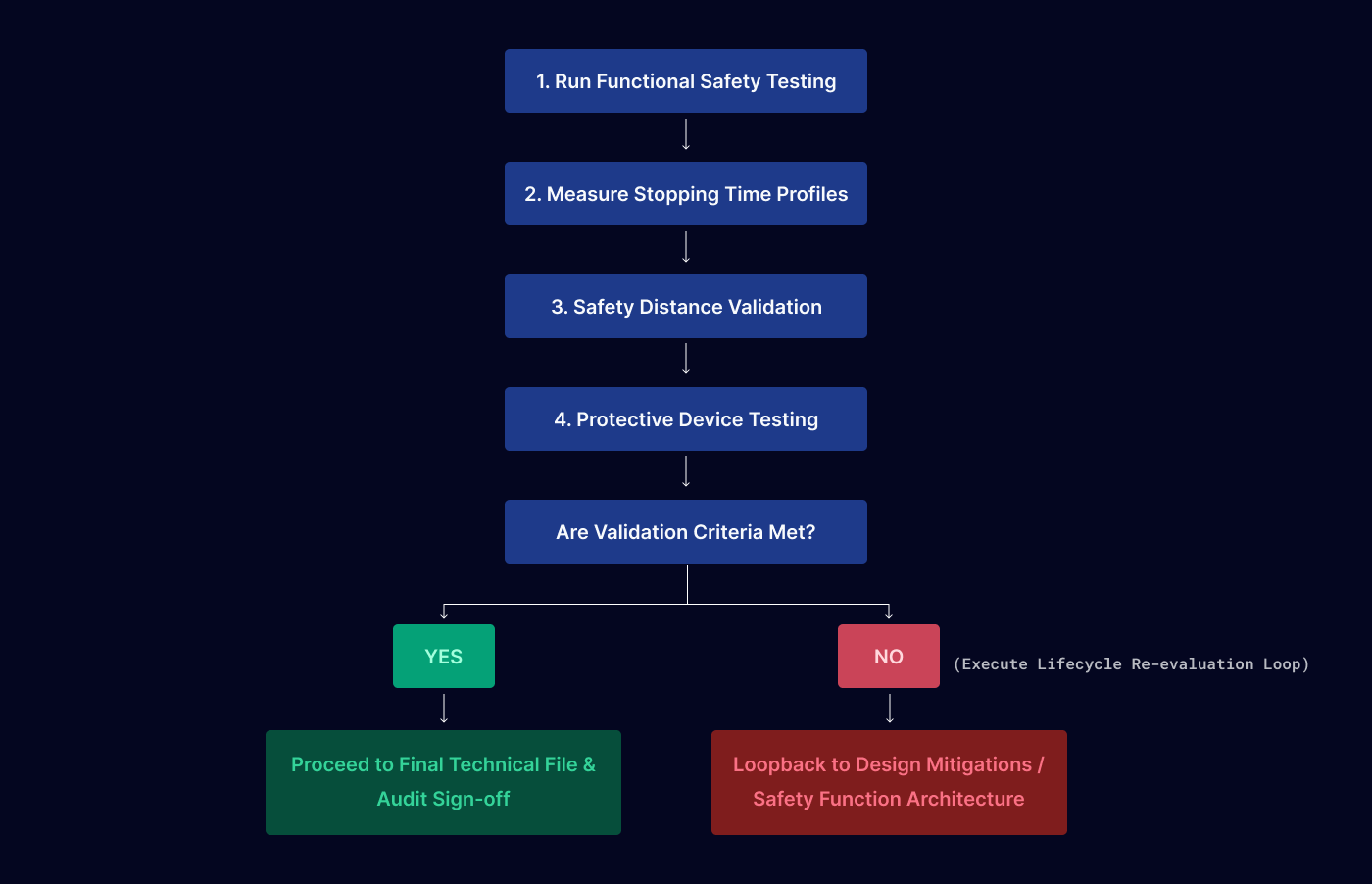
This verification process relies on four core empirical validation techniques:
Functional Testing:
Rigorously exercising all safety-related control loop hardware, diagnostic routines, and software logic loops under simulated fault states.
Stopping Time Measurement:
Utilizing physical data logging tools to measure the exact millisecond delay between a safety trigger and the complete cessation of dangerous mechanical motion.
Safety Distance Validation:
Calculating and physically testing protective sensor position distances to confirm that an operator crossing a light curtain cannot reach a pinch point before the system completes a safe-state transition.
Protective Device Testing:
Executing strict pass/fail test sequences on laser scanners, pressure mats, and interlocking hardware interfaces to verify environmental resilience and eliminate systematic configuration blind spots.
Mandatory Functional Safety Documentation Suite
An ISO 12100 risk assessment and its subsequent IEC 61508 transition are incomplete without a structured, audit-ready technical file. This framework demands three distinct, highly integrated engineering documents:
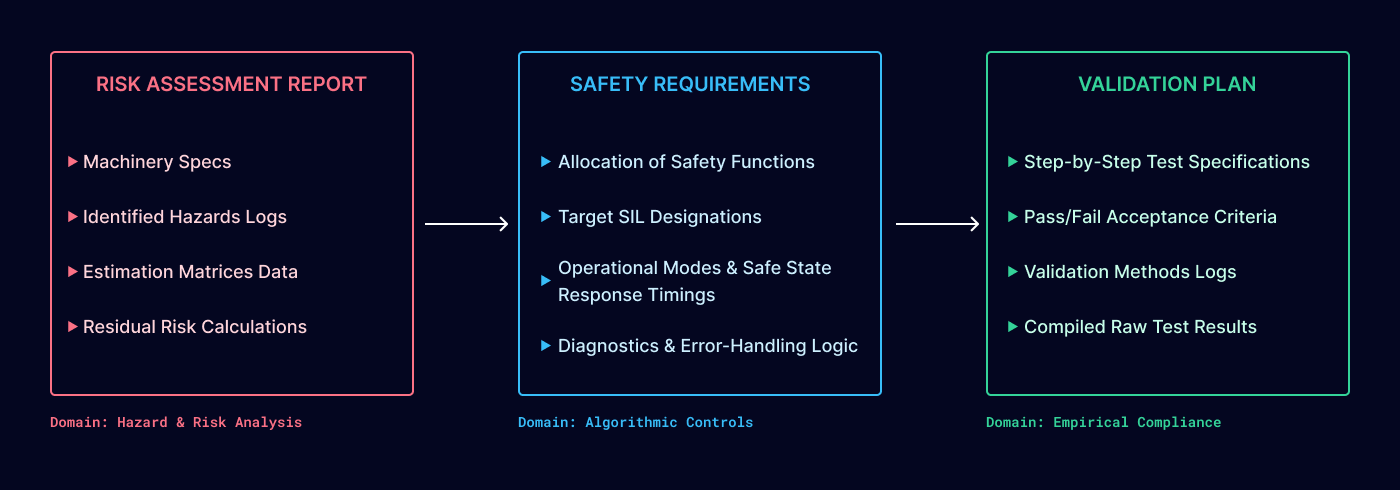
Risk Assessment Report:
Houses the definitive engineering baseline, capturing complete machinery specifications, systemic hazard logs, raw risk estimation matrices, implementation records of chosen risk reduction measures, and final residual risk index calculations.
Safety Requirements Specification (SRS):
Defines the exact technical parameters of the safety functions, including target SIL metrics, operational profiles, maximum required safe state response times, and system error-handling configurations.
Validation Plan:
Provides the physical proof ledger, containing explicit step-by-step test specifications, quantitative acceptance criteria, validation methods, and the compiled raw test data logs verifying compliant field performance.
Because risk assessment is a strictly iterative engineering process, this entire documentation suite must be treated as a living, version-controlled repository. It must be continuously updated and audited throughout the autonomous system's operational lifecycle to account for field modifications, environmental changes, or system updates.