The V-Model is a structural, graphical representation of a systems development lifecycle that serves as a technical roadmap for engineering safety-critical systems. By clearly mapping out each consecutive phase of the design process against its corresponding validation and verification step, the V-Model ensures a systematic approach to both architecture development and software/hardware testing.
This framework is essential for engineers navigating the complexities of high-integrity systems, visually illustrating the relationship between initial definition phases (the left descending side of the "V") and corresponding integration and test execution phases (the right ascending side of the "V").
Cross-Industry Implementation Profiles
The structured framework of the V-Model is utilized across multiple high-risk engineering sectors to maintain an organized development pipeline and force early defect detection, maximizing overall system reliability:
Automotive Engineering:
Under the strict mandates of the international standard
ISO 26262
, the V-Model is the benchmark framework required to develop embedded electronics and safety-critical vehicle components, acting as the baseline to achieve formal compliance audits.
Aerospace and Defense:
Avionics architectures and mission-critical military platforms rely on the V-Model to handle ultra-complex system interactions, satisfying stringent regulatory tracks and lowering systematic error rates.
Healthcare and Medical Technology:
Medical device manufacturers deploy the framework to ensure diagnostic and surgical instrumentation conform to strict regulatory approval standards, protecting patient safety through rigorous verification.
Industrial Robotics and Rail Transit:
While standards in the robotics (ISO 3691-4) and rail (EN 50126) sectors may not always explicitly draw the full "V" graphic in their documentation, their compliance lifecycles adhere strictly to its underlying principles of systematic derivation and decoupled, independent testing.
Mapping the Left and Right Sides of the V-Model
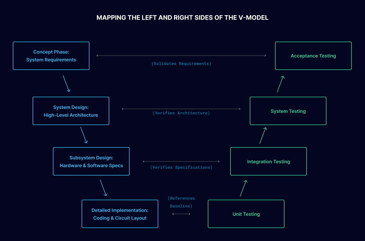
The V-Model enforces a strict technical dependency where an engineering team cannot execute a testing tier on the right side of the model without directly referencing the specific design parameters established on the corresponding left side.
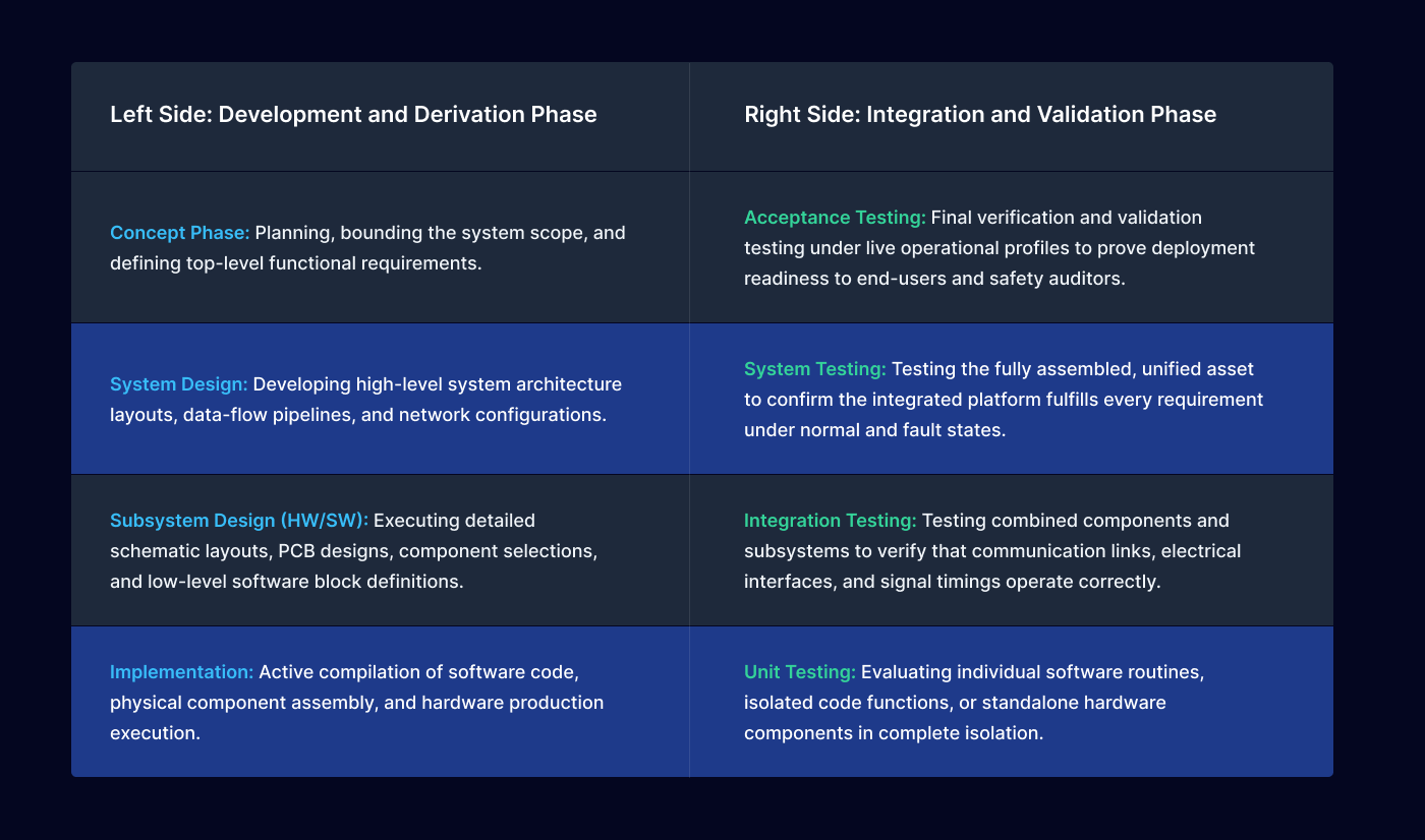
Execution Matrix of the Development and Testing Phases
Implementing Functional Safety Step-by-Step
Integrating functional safety within the V-Model requires specific, auditable actions across seven progressive lifecycle checkpoints:
1. Management of Functional Safety
Establish an absolute, top-down safety culture across the development organization. This requires explicitly defining technical roles, mapping clear ownership parameters for safety-critical tasks, appointing an independent Functional Safety Manager, and scheduling formal safety lifecycle coordination tasks early in the project timeline.
2. Concept Definition and Safety Initialization
Formally define the physical and logical boundaries of the equipment under control (EUC). Concurrently, launch active safety lifecycle tasks by executing a comprehensive Hazard Analysis and Risk Assessment (HARA) to identify potential failure hazards and assign corresponding Safety Integrity Level (SIL) or Automotive Safety Integrity Level (ASIL) targets.
3. System Design and Safety Requirement Allocation
Translate high-level functional safety goals into clear Technical Safety Requirements (TSR). Architects must distribute these safety requirements directly down into specific system components, configuring internal diagnostics, fail-safe protocols, and the primary system design layout to minimize failure propagation.
4. Subsystem and Component Development
Design and build out the targeted hardware components and software modules to comply with allocated safety metrics. This requires executing detailed Failure Modes and Effects Analyses (FMEA) or Fault Tree Analyses (FTA) to catch component defects, backed by automated unit verification loops.
5. Production and Operation Planning
Ensure that the final manufacturing, assembly, and software-flashing processes utilize rigorous quality control measures to prevent the introduction of physical or programmatic assembly errors. This step extends to outlining strict operational manuals, lock-out/tag-out (LOTO) field procedures, and operator training frameworks.
6. Supporting Processes and Change Management
Sustain continuous compliance through automated requirement management tooling (such as DOORS or Polarion). Any modification to software code or hardware layouts must pass through a formal engineering change control loop, executing automated regression testing and updating validation records to preserve traceability.
7. Decommissioning and System Disposal
Plan and document the final decommissioning lifecycle phase. Engineers must establish clear procedural rules to guarantee that when an asset reaches its end-of-life status, it can be systematically powered down, dismantled, and disposed of without introducing physical or environmental safety hazards.
Core Engineering Advantages
Systematic Risk Reduction:
Integrating hazard analysis directly into early development steps identifies and neutralizes critical risks before they reach downstream engineering phases.
Minimized Development Costs:
Catching component errors and specification gaps during the requirements phase avoids incredibly expensive late-stage hardware re-spins and product deployment delays.
Unbroken Traceability:
Forcing clear mapping between design requirements and validation test items creates an audit-ready compliance trail that simplifies third-party certification checks.
Optimized Stakeholder Communication:
Providing a unified, structured framework establishes a shared technical language, aligning safety managers, core design engineers, test technicians, and corporate leadership behind identical quality metrics.