Introduction
For designers of robotic systems seeking IEC 61508 certification, performing a thorough risk assessment according to ISO 12100 is a crucial first step. This article guides you through the process, providing practical examples relevant to robotic applications.
Understanding the Relationship
Before diving into the risk assessment process, it's important to understand how ISO 12100 and IEC 61508 complement each other:
ISO 12100 provides the foundational methodology for identifying hazards and assessing risks
IEC 61508 builds upon this by specifying requirements for electrical/electronic/programmable electronic (E/E/PE) safety-related systems
The Risk Assessment Process
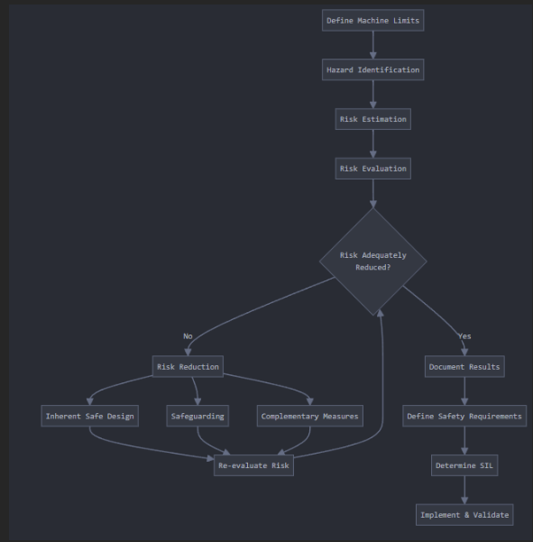
Figure 1: Risk Assessment Process
Step 1: Define the Limits of the Machinery
Consider all phases of the robotic system's lifecycle, including:
Physical limits (range of motion, speed, force)
Time limits (expected lifetime, maintenance intervals)
Use limits (intended operation modes, user interactions)
Example: For a collaborative robot arm in a manufacturing cell:
Physical: 1.4m reach, 15kg payload, 1.5 m/s maximum speed
Time: 10-year expected lifetime, quarterly maintenance
Use: Pick-and-place operations, direct human interaction during teaching
Step 2: Hazard Identification
Systematically identify all potential hazards, considering:
Mechanical hazards (crushing, shearing, impact)
Electrical hazards
Thermal hazards
Control system failures
Example: For our collaborative robot:
Crushing hazard between robot arm and fixed objects
Impact hazard during unexpected movements
Electrical hazard from exposed terminals during maintenance
Control system failure leading to uncontrolled motion
Step 3: Risk Estimation
For each hazard, estimate:
Severity of potential harm
Probability of occurrence, considering:
Exposure frequency
Probability of hazardous event
Possibility of avoidance
Example Risk Estimation Matrix: Severity levels:
S1: Minor injury (reversible)
S2: Serious injury (irreversible)
S3: Death
Probability levels:
P1: Rare
P2: Possible
P3: Likely
Step 4: Risk Evaluation
Determine if risk reduction is required based on the estimated risk level. This evaluation will feed directly into your IEC 61508 safety requirements. Example: For a crushing hazard between robot and workpiece:
Severity: S2 (potential for serious injury)
Probability: P2 (possible during normal operation)
Result: Risk reduction required
Risk Reduction Measures
Three-Step Method
Inherently Safe Design Measures:
Eliminate pinch points through design
Reduce maximum force/speed capabilities
Implement mechanical stops
Use fail-safe principles
Example: For a collaborative robot:
Design rounded edges and smooth surfaces
Limit joint torques through mechanical design
Implement backdrivable joints
Safeguarding and Complementary Protective Measures:
Guards and protective devices
Emergency stop systems
Safety-rated monitored stop
Speed and separation monitoring
Example:
Safety laser scanner for presence detection
Pressure-sensitive mats in work area
Two-hand control devices for dangerous operation
Information for Use:
Warning signs and signals
Operating procedures
Training requirements
Maintenance instructions
SIL Determination Process
Step 1: Consequence Analysis
Evaluate the consequence of hazardous events:
C1: Minor injury
C2: Serious permanent injury to one or more persons; death to one person
C3: Death to several people
C4: Very many people killed
Step 2: Frequency and Exposure Time
Assess frequency of exposure:
F1: Rare to more often
F2: Frequent to continuous
Step 3: Possibility of Avoiding Hazard
Consider avoidance factors:
P1: Possible under specific conditions
P2: Scarcely possible
Step 4: Probability of Unwanted Occurrence
Evaluate probability:
W1: Very slight probability
W2: Slight probability
W3: Relatively high probability
SIL Assignment Example
For a robot emergency stop function:
Consequence: C2 (potential death)
Frequency: F2 (frequent exposure)
Possibility of avoidance: P2 (rarely possible)
Probability: W2 (slight) Result: SIL 2 requirement
Risk Reduction Verification
For each implemented measure:
Verify effectiveness
Ensure no new hazards introduced
Document validation results
Update risk assessment
Example verification methods:
Functional testing of safety systems
Measurement of stopping times
Validation of safety distances
Testing of protective devices
Documentation and Implementation
Required Documentation
Risk Assessment Report:
Machinery specifications
Hazards identified
Risk estimation results
Risk reduction measures
Residual risks
Safety Requirements Specification:
Safety functions
SIL requirements
Operating modes
Response times
Error handling
Validation Plan:
Test specifications
Acceptance criteria
Validation methods
Test results
Conclusion
A thorough ISO 12100 risk assessment provides the foundation for IEC 61508 certification. By following this structured approach and maintaining detailed documentation, you'll be well-prepared for the certification process. Remember that risk assessment is an iterative process - continue to monitor and update your assessment throughout the system's lifecycle.